Friday, February 19, 2010

What happened to the last two weeks?

So, not too much happening on the hardware front these last couple of weeks. I got a new (small) antenna for the plane. Previously, we were using a piece of wire I ripped out of my old laptop, but I think that might have been causing problems, especially at long distances. So now, there's a cool little antenna sticking out of the plane right by the GPS receiver.

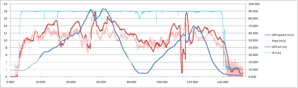
The bulk of the last couple weeks has been spent working on software. The screenshots here are from the latest version of our homemade cockpit app. This runs on my laptop when we're flying and displays telemetry from the plane in real time. It can also save logs of the flights and plays them back later. The newest additions feature-wise are the Altimeter and the Heading Indicator instruments that show up on the bottom-right. If you're wondering, the units on the Altimeter are 1000/100/10 meters.

Here's a few screenshots. Take a look at the altitude in the last one -- 469 meters is a little more that 1,500 ft!

GlassCockpit1 GlassCockpit1 GlassCockpit1 GlassCockpit1

Tuesday, February 2, 2010

Test Sensors -- Round 2 -- Flight!

After a bit of work on the wireless link (which was causing some problems with the earlier flights), we went back out for a second day of test flights.

Here's a .kml file (Google Earth) showing the GPS track from the 5 test flights we did last Sunday. The altitude data has been included as well, so be sure to pan the view to see the vertical axis:
Download

All Flights   Flight 4
Click for a larger view.

Monday, February 1, 2010

Test Sensors - Results

So, the first flights of our sensor platform took place on Jan 23rd. This is a sample of the data we got back:

This is a graph showing basic telemetry data from the aircraft during a flight. The data is sent from the Arduino to the xbee radio, received by a ground station, logged, and then later processed with Excel. Of note, the pilot performed a low altitude pass at approximately 90 seconds into the recorded session, and the large spikes beginning around 110 seconds are from a vertical flip:

Click for a larger view.

Sunday, January 31, 2010

Test Sensors

Here are some pictures of the sensors that Matt has put together for the initial testing of the platform. Click the images to be taken to larger versions.

The R/C aircraft is a Hobbyzone "Super Cub". The light weight and high power-to-weight ratio makes it an ideal body to get the sensor platform into flight and protect the more sensitive components from any inevitable crashes:


An Arduino is mounted in the main cargo bay. It collects data from a number of sensors and sends the information to an xbee radio to be transmitted to a ground station for recording:


A GPS chip is used to gather position data and altitude, and it calculates ground speed velocity:


An IR sensor mounted to the bottom of the plane provides more accurate altitude measurements, but only when near the ground:


A pitot tube arrangement provides air speed information:


A 3-axis gyroscope is scavenged from the Wii Motion+ element, and a 3-axis accelerometer is scavenged from the Wii Nunchuck. These two devices provide complementary motion data to define the motion of the aircraft through space:

Science Greg

Nifty blog.

An update on what I'm doing: I am working a simulation of the aircraft in Matlab. I'm using a vortex-lattice method to simulate the aerodynamics. Once the aerodynamics have been accurately simulated, I'm going implement a controller. This will allow us to test the controller without crashing the plane. Kenton will hopefully help me write the controller, because I don't really know how to yet.

The vortex-lattice method does have some limitations. It assumes a linear Cl vs alpha curve, which means it does not model stall speed angle of attack effectively. However, our controller should never allow that to happen anyways. Also, it does not model the thickness of the wing or the boundary layer. These two mostly effect the drag anyways, so that limitation will be addressed by including a CDi (Induced drag) into the calculations.

Saturday, January 30, 2010

Welcome

This site will be documenting the development of a independently-designed, automated Unmanned Aerial Vehicle. The target of this project is a vehicle which will be capable of maintaining stable flight and navigating a predetermined route. The vehicle will maintain contact with ground stations to communicate location data, other telemetry, and gathered imagery.